A plant operating an industrial ammonia (NH₃) refrigeration system needed an assessment of its pipework condition without exposing it. The installation runs under cold insulation, and shutting it down means cutting refrigeration to the entire facility. The scope covered 100 measurement points on pipework from DN15 to DN80 with a nominal wall thickness of 2.3 to 3.2 mm. The task was to measure pipe wall thickness without removing the insulation and without taking the system out of service.
Key Results
- 100 measurement points inspected with no insulation removal and no shutdown of the refrigeration system.
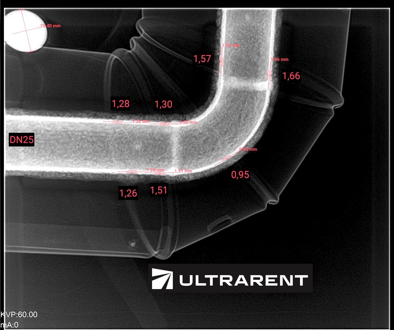
- Several critical locations found where wall thickness had dropped below 1 mm against a nominal 2.3–3.2 mm — a loss of more than 60% of the original section.
- Additionally, outside the scope of work, lack of penetration was visible in welds on the radiographs; these indications were passed to the client with a recommendation for separate weld inspection.
- Specific repair locations identified instead of a blind replacement of pipe sections.
- Digital radiographs archived as a baseline for future inspections.
The Challenge: A System That Cannot Be Opened or Stopped
Ammonia pipework operates across a wide temperature range — from well below zero on suction and liquid lines to high temperatures on the compressor discharge side. The cold side is insulated and vapour-sealed, because without that barrier moisture condenses and ice forms.
And that is precisely where the problem develops. Moisture condensing on the cold pipe surface creates conditions for corrosion under insulation (CUI), entirely invisible from the outside. With a nominal wall of 2.3–3.2 mm the margin is minimal: a loss of around one millimetre already removes most of the strength.
Conventional ultrasonic thickness measurement (UTT) would require exposing every point, breaching the vapour barrier, erecting access and reinstating the insulation afterwards. It also gives a point reading only, with no guarantee of hitting the thinnest spot. Ammonia adds a further argument: it is a toxic and irritant medium, so any intervention in a live system carries risk, and shutting it down means losing refrigeration across the whole plant.
The Solution: Digital Radiography Through the Insulation
We applied digital radiography (DR) using the tangential technique to EN ISO 20769-1 and double-wall measurement to EN ISO 20769-2. The setup comprised:
- an iRay 1012MA digital detector,
- a Se-75 gamma source in a Gammamat SE projector,
- dedicated software for processing and measurement on digital radiographs.
The choice of source is deliberate. The beam has to pass through the cladding, the insulation layer and both pipe walls, so the actual penetrated thickness is many times the nominal wall thickness. Selenium-75 gives better image contrast than higher-energy sources, which at these wall thicknesses determines whether a reliable measurement is possible at all. The compact Gammamat SE projector allows work in congested pipe racks and close to structural steel.
The key difference from contact methods: a radiograph shows the wall profile across the full width of the image, not a single point. Both localised corrosion loss and weld geometry are visible — which is why weld workmanship defects surfaced alongside the thickness measurements.
The Results: Losses Below 1 mm and Weld Defects
Of the 100 points inspected, several proved critical — measured wall thickness had fallen below 1 mm against a nominal 2.3–3.2 mm. That is a loss of over 60% of the original section, in a pressurised system carrying ammonia.
Independently of corrosion, the radiographs revealed lack of penetration in welds — defects dating back to the original installation. Weld assessment was not part of this scope, and testing was carried out to the standards applicable to thickness measurement. We nevertheless passed these indications to the client with a recommendation for separate weld inspection, because lack of penetration reduces the effective section of the joint and creates a notch from which cracking can initiate. In a system running through changing temperatures and defrost cycles, that is a real risk of loss of containment.
The client received a list of specific locations requiring action rather than an estimate of overall condition. Repairs could be planned point by point during a controlled shutdown instead of being forced by a failure — which with ammonia means not only lost production but evacuation and emergency procedures. The set of digital radiographs also serves as a baseline for comparison at the next inspection, making it possible to track the rate of wall loss over time.
We used a comparable approach — assessing what is hidden under insulation without removing it — in our case study on press fitting inspection. Where full wall mapping is required, corrosion mapping (CM) is the natural extension.
Client Quote
“You cannot simply open up an ammonia system, and you cannot simply stop it — every insulation strip-out is a risk and a cost, and a shutdown means no refrigeration anywhere in the plant. Testing through the insulation gave us a picture of the pipework condition without touching a live system. Most importantly, we received specific locations to repair, including points with wall thickness far below nominal that we had no idea about. We now know where to act instead of replacing sections on a hunch.”
Do you operate pipework running under insulation? Get in touch — we will assess its condition without removing the insulation and without shutting the system down.