In brief
- Single-sided access — the reason the technique exists
- No system pressurisation — no medium, no hydrotest, no isolation
- Immediate visual result — bubbles appear in the window during the test
- Standard technique for tank floors under API 650 and API 653
- Finds through-wall paths only — not a substitute for volumetric inspection
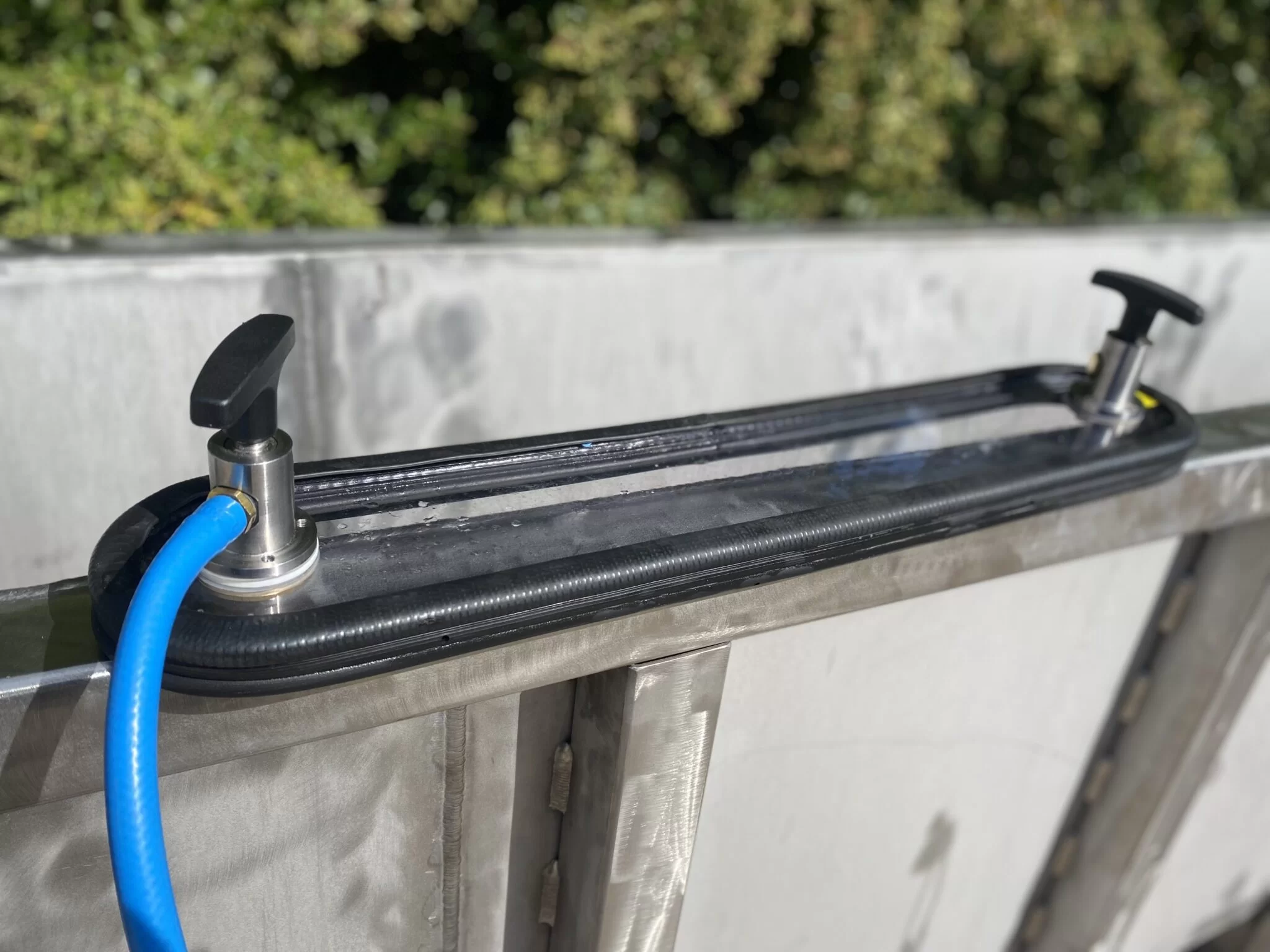
Vacuum box leak testing places a sealed, transparent-windowed box over a weld coated with an indicating solution and draws a controlled vacuum inside. Where a through-wall path exists, atmospheric pressure on the far side pushes air through it, and bubbles form at the leak — visible immediately through the window.
The technique exists because of one constraint that recurs constantly in tank and vessel work: you often cannot get to the other side. A tank floor sits on sand or concrete. A shell-to-bottom joint has soil against it. A double-bottom compartment cannot be filled. Vacuum box testing turns the atmosphere itself into the pressure source and needs access from one surface only.
Where it is used
- Tank floor welds — lap welds and butt welds in the bottom plates
- Shell-to-bottom joints — the annular weld, a common corrosion and cracking location
- Lap and fillet welds generally, where a pressure test would not load the joint correctly
- Ship hull plating and double-bottom structures
- Repair welds in floors and shells during a shutdown, where re-testing the whole tank is not feasible
- New construction acceptance under API 650, and in-service inspection under API 653
The commercial context is usually a tank outage. The tank is out of service, the clock is running, and the floor welds must be demonstrated tight before the tank can be returned to duty. Vacuum box testing suits that because it requires no filling, no pressurisation and no isolation — and the result is available as the box moves along the weld.
The technique
- Surface preparation. Loose scale, rust, coating residue, dirt and oil are removed from the weld and the sealing path. Contamination has two separate effects: it can block a leak path so a leaking weld passes, and it can prevent the gasket sealing so no vacuum can be achieved.
- Apply the indicating solution. A film of solution is applied over the weld and the adjacent metal. The solution must produce stable bubbles over the hold period, resist freezing at ambient temperature, and be compatible with the material — chloride content matters on stainless steel for the same reason it matters in penetrant testing.
- Place the box and evacuate. The box is positioned so the weld runs through its viewing area, and vacuum is drawn to the level specified in the procedure. Gauge and relief valve confirm and limit the level reached.
- Hold and observe. The vacuum is held for the required time while the operator watches through the window under adequate illumination. Observation must continue for the full hold period — small leaks take time to form visible bubbles, and a box moved on early is a box that found nothing because nobody waited.
- Mark and record. Indications are marked on the plate for repair and recorded against a location map, referenced to the tank drawing or inspection plan.
- Advance with overlap. Successive placements overlap so no length of weld falls between two boxes. Overlap is where coverage is won or lost, and a scan record that does not demonstrate it does not demonstrate full examination.
Box types
Flat boxes — for floor plate welds and flat surfaces. The workhorse.
Corner boxes — shaped to seal against the shell-to-bottom joint, where a flat box cannot make contact on both surfaces.
Segmented and specialised boxes — for curved surfaces, nozzle welds and geometry that standard boxes cannot seal against.
Box selection is not a detail. A box that cannot seal against the geometry produces either no vacuum or an unreliable one, and no amount of hold time compensates.
Parameters that govern the result
Vacuum level. Set by the governing standard and the procedure. Too low and small leaks do not draw enough air to bubble; excessive vacuum risks distorting thin plate. Values are specified in ASME BPVC Section V Article 10 Appendix II and in API 650 — confirm against the edition in force for the project.
Hold time. Also specified, and routinely shortened in practice under schedule pressure. This is the most common way vacuum box testing is done badly.
Illumination. Bubbles in a soap film are low-contrast. Insufficient light at the viewing window is a real cause of missed indications, and lighting requirements form part of the procedure.
Ambient temperature. Cold weather thickens or freezes the solution and reduces bubble formation; heat dries the film before the hold period ends. Both need addressing with an appropriate solution and, where necessary, a change in test conditions.
Gasket condition. A worn or damaged seal prevents the box holding vacuum and wastes the placement. Gaskets are consumables and should be treated as such.
Limitations
Through-wall paths only. A defect that does not yet penetrate the wall produces no leak and will not be found. Vacuum box testing confirms tightness, not soundness — pair it with a volumetric method where structural integrity is the concern.
No sizing. The technique locates a leak. It does not tell you how large the defect is, how deep it runs, or what caused it.
Sensitivity floor. Bubble techniques detect leak rates in the region of 10⁻³ to 10⁻⁴ mbar·l/s under favourable conditions. Leaks below that require a tracer gas method. Where a specific leak rate is required, EN 1779 provides the criteria for choosing a method against it.
Geometry. The box must seal. Complex geometry, obstructions, nozzles and attachments may leave lengths of weld that no available box can cover — and these should be identified on the drawing before mobilisation, not discovered on the floor.
Temporarily blocked leaks. Debris, sealant, product residue or corrosion product can plug a path so it passes the test and opens later under service pressure or thermal cycling.
Rate of progress. Coverage advances one box length at a time, and long weld runs take proportionate time. This is a scheduling reality worth building into the outage plan.
Standards
| Scope | Standard |
|---|
| Vacuum box technique | ASME BPVC Section V, Article 10, Appendix II |
| Leak testing — general | ASME BPVC Section V, Article 10 |
| Bubble emission techniques | EN 1593 |
| Criteria for method and technique selection | EN 1779 |
| Welded tanks for oil storage — construction and testing | API 650 |
| Tank inspection, repair, alteration and reconstruction | API 653 |
| Vocabulary | ISO 20484 |
| Personnel certification | ISO 9712 |
Evaluation against acceptance criteria requires ISO 9712 Level 2 as a minimum; procedure approval requires Level 3.
Frequently asked questions
Why use a vacuum box instead of a pressure test?
Because access to the second surface is often impossible — a tank floor rests on its foundation — and because filling and pressurising a tank to test a floor weld is slow, expensive and sometimes unsafe. The vacuum box needs one side only and no test medium.
What vacuum level and hold time are required?
Both are specified by the governing standard and the written procedure, primarily ASME BPVC Section V Article 10 Appendix II and API 650. Confirm the values for the edition applicable to your project rather than assuming a general figure.
How sensitive is vacuum box testing?
In the region of 10⁻³ to 10⁻⁴ mbar·l/s under favourable conditions — comparable to other bubble methods. For finer leak rates, tracer gas methods are required.
Can it be used on curved surfaces and shell-to-bottom joints?
Yes, with appropriately shaped boxes. Corner boxes seal against the annular joint; segmented boxes handle curvature. The constraint is whether a box can seal against the geometry.
Does the tank have to be out of service?
The area under test must be accessible, clean and dry, and the far side must be at atmospheric pressure. In practice this normally means an outage for floor testing, though localised repair welds can often be tested during a short shutdown.
Does a passed vacuum box test mean the weld is sound?
No. It means the weld is tight at the time of test. A part-through defect produces no leak and can grow in service. Where soundness matters, combine with volumetric inspection.
Planning a tank outage?
We perform vacuum box leak testing on floors, shell-to-bottom joints and repair welds to API 650, API 653 and ASME V, across Europe — with flat, corner and segmented boxes for the geometry on site.
→ Leak testing services · Request a quote