In brief
- They find different things — ultrasonic testing favours planar defects, radiography favours volumetric ones
- The product form matters — welds, castings, forgings and plate each favour a different balance
- Access differs — UT needs one side; RT needs both sides of the wall
- Radiography needs a controlled area; ultrasonic testing does not
- Many codes require both, because each covers the other’s weakness
Ultrasonic testing (UT) and radiographic testing (RT) are the two volumetric NDT methods used to look inside welds, castings, forgings and plate. They are often treated as alternatives. In practice they answer different questions, and the right choice depends on what you are inspecting, what defect you are worried about, and what the site allows.
How each method works
Ultrasonic testing sends a short pulse of high-frequency sound into the material. Wherever it meets a boundary — the back wall, a crack, an inclusion — part of the energy reflects back, and the instrument times and measures it. From that echo an inspector determines how deep the reflector lies and how large it is relative to a reference. See ultrasonic testing: how it works.
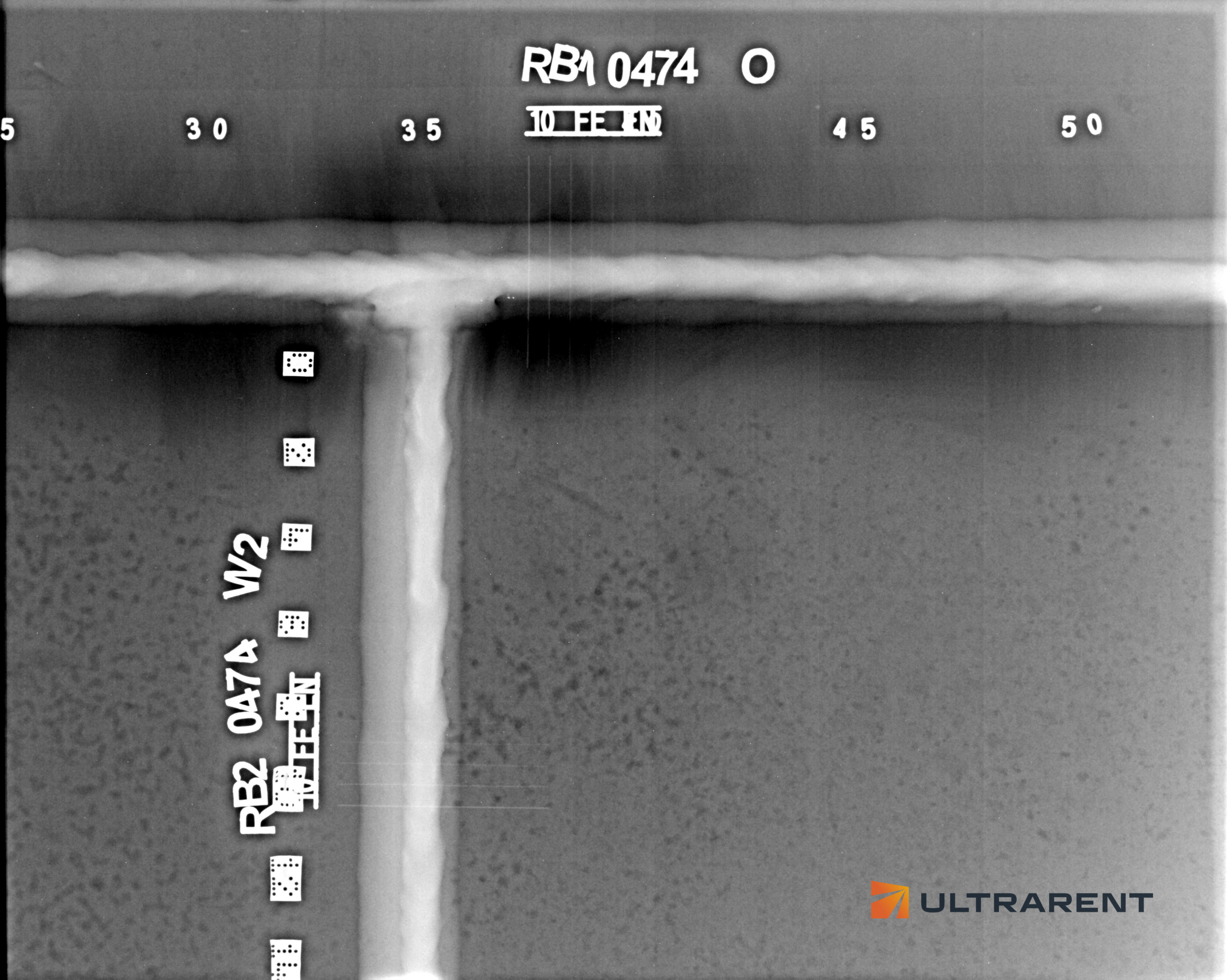
Radiographic testing passes ionising radiation through the component and records the transmitted intensity on film or a digital detector. Material that is thinner or less dense — a pore, a slag inclusion, a missing root — absorbs less and appears darker. See radiographic testing of welds and digital radiography.
What each finds, and what each misses
This is the core of the comparison.
| Discontinuity | Ultrasonic testing | Radiography |
|---|
| Cracks | Strong, if the beam angle is right | Only when favourably oriented to the beam |
| Lack of fusion | Strong | Frequently missed on near-vertical fusion faces |
| Lack of penetration | Strong | Strong |
| Gas pores, porosity | Weaker, especially when fine and distributed | Strong |
| Slag and other inclusions | Good | Strong |
| Laminations in plate | Strong | Missed (they lie parallel to the surface) |
| Through-wall size of a defect | Possible (best with TOFD or PAUT) | Not available |
The pattern is consistent: ultrasonic testing is the stronger method for planar defects, radiography for volumetric ones. A tight crack perpendicular to a radiographic beam produces almost no thickness difference, so almost no contrast. An ultrasonic beam parallel to a planar defect reflects almost nothing, which is why weld inspection uses several angles and scanning directions.
Welds
Both are used, often together. UT, and especially PAUT and TOFD, cover the planar defects that govern structural integrity. Radiography covers fine porosity and gives a permanent image. For when PAUT can replace radiography and what to check first, see PAUT instead of radiography.
Castings
Castings favour radiography more than welds do. Their geometry is irregular, their sections are often thick and variable, and typical defects — shrinkage cavities, porosity, sand and slag inclusions — are volumetric. Ultrasonic testing is harder here: coarse grain, particularly in grey cast iron, scatters and attenuates the beam, irregular shapes limit probe contact, and cast defects tend to be rough, weak reflectors that are difficult to characterise. UT of castings is governed by EN 12680 and film radiography by EN 12681-1, and the standard has to match the material and its service duty.
Forgings
Forgings favour ultrasonic testing. Their defects — internal discontinuities from the forging process — are often planar and lie where radiography sees them poorly, and their sections are frequently thick. Ultrasonic examination follows EN 10228-3 for ferritic and martensitic steel and EN 10228-4 for austenitic and duplex.
Plate, bar and pipe
Rolled products favour ultrasonic testing almost entirely. Their characteristic defect is the lamination, which lies parallel to the surface and is invisible to radiography. Plate is examined to EN 10160, and tube and pipe to ISO 10893-8 and related parts.
Practical differences on site
| Ultrasonic testing | Radiography |
|---|
| Access | One side, prepared surface | Both sides of the wall |
| Radiation controls | None | Controlled area, cordoning, dose monitoring |
| Work nearby | Continues | Interrupted within the controlled area |
| Result available | Immediately | Minutes (digital) to hours (film) |
| Thickness limit | Set mainly by attenuation in the material | Set by source energy |
| Surface preparation | Demanding: dressed, clean, coupled | Less demanding: clean of anything that distorts the image |
| Record | Encoded data (PAUT, TOFD) or a written report | A permanent image |
| Operator dependence | High for conventional UT; lower for encoded techniques | Moderate; the image can be re-read by a second inspector |
Two points are easy to overlook. First, a conventional manual UT result is only as good as the operator and leaves little behind afterwards, which is why encoded PAUT and TOFD scans are preferred where a verifiable record matters. Second, radiography needs access to both sides of the wall, which is not the same as access to the inside of an object: small-bore pipe is radiographed entirely from outside with a double-wall technique.
Choosing between them
Work through the questions in order:
- What does the specification require? If it names one method, that settles it unless a substitution is formally approved.
- Which defect worries you most? Cracks and lack of fusion point to ultrasonic testing. Porosity and inclusions point to radiography.
- What is the product? Plate and forgings lean towards UT, castings towards RT, welds towards both.
- Can you reach it? One-sided access rules out radiography. A weld that cannot be scanned rules out PAUT.
- Can the site stop? If a controlled area is not possible, ultrasonic methods become the practical choice.
- What record is needed? A permanent image or a re-analysable scan.
Why many codes require both
Because the methods fail in opposite places. A programme using only radiography can pass a joint with a tight lack-of-fusion plane. A programme using only ultrasonics can pass a joint with fine porosity. Combining them covers both, and is generally a stronger scope than either alone. Where a single method has to be chosen, the questions above decide it, but it is worth asking what the other method would have found.
Frequently asked questions
Which is better, ultrasonic testing or radiography?
Neither is better in every case. Ultrasonic testing is stronger for planar defects, thick sections and depth sizing. Radiography is stronger for volumetric defects and gives a permanent image. The choice depends on the defect, the product, the access and the specification.
Can ultrasonic testing detect cracks that radiography misses?
Yes. Planar defects such as cracks and lack of fusion are where UT outperforms radiography, which frequently misses tight cracks lying perpendicular to the beam.
Why is radiography preferred for castings?
Castings have irregular geometry, thick variable sections and volumetric defects, and coarse grain makes ultrasonic testing difficult, especially in grey cast iron.
Does ultrasonic testing need a controlled area?
No. Radiography does. This is often the deciding factor where production cannot stop.
Do I need both methods?
Often. Many codes and specifications require both, because each covers the other’s weakness. Your specification and the nature of the component decide.