In brief
- PAUT can replace radiography on many welds — but only where the specification and code allow it
- It is stronger on planar defects (cracks, lack of fusion) and gives through-wall sizing; radiography is stronger on fine porosity
- No controlled area — inspection proceeds while other trades keep working
- The decision is made on the project code, not on which method is more modern
- Often the best scope uses both
Radiography has been the default volumetric method for welds for decades, and a great many specifications still name it. Phased array ultrasonic testing (PAUT) is now accepted as an alternative in a growing number of them — and on many projects it is the more practical choice. This article sets out when replacing radiography with PAUT is sound, when it is not, and what to check before changing a scope.
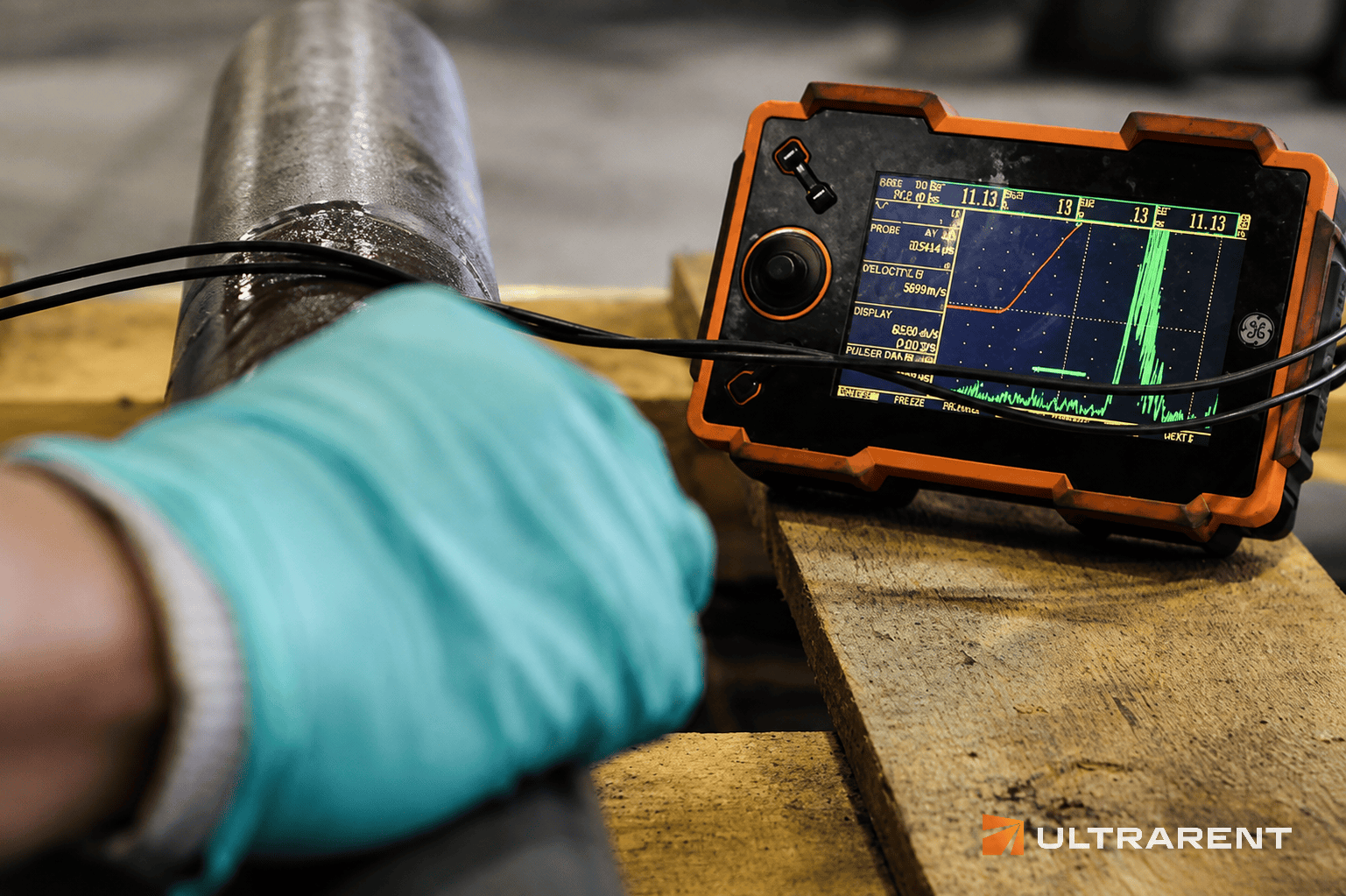
The physics decides what each method finds
The two methods do not see the same things, and that is the starting point for any comparison.
Radiography records differences in absorbed thickness along the beam path. Pores, slag and tungsten inclusions, and lack of penetration all change that thickness and show clearly. A planar defect with almost no opening, lying perpendicular to the beam, changes it hardly at all — so tight cracks and lack of side-wall fusion are frequently missed. This is physics, not operator skill. See radiographic testing of welds.
PAUT works from reflections and diffraction. A planar defect is a good reflector, and sweeping the beam through a range of angles means a defect missed at one angle is usually caught at another. Fine, distributed porosity is the opposite case: it reflects weakly and is harder to characterise. See phased array ultrasonic testing.
The defects that matter most for joint integrity — cracks and lack of fusion — are exactly the planar ones. That is the technical case for PAUT, and it is stronger than the speed argument that usually gets quoted.
Where PAUT is the better choice
- Planar defect risk. Thick-section butt welds, fatigue-loaded joints and high-integrity pressure work, where cracks and lack of fusion govern.
- Through-wall sizing is needed. Fitness-for-service decisions depend on defect height, and radiography cannot provide it at all.
- Radiography is operationally impractical. Where a controlled area cannot be established or production cannot stop, PAUT removes the constraint entirely, because there is no radiation.
- Thick sections. Radiography is limited by source energy; ultrasound is limited mainly by the material.
- Immediate results and a recorded scan. The result is read on site, and an encoded scan shows exactly which volume was examined.
Two examples from our own projects
City-centre pipework. On a district heating upgrade, welds were being made in trenches beside a busy street and residential buildings. Radiography would have meant a controlled area for every exposure and halting traffic. Mechanised PAUT let inspection run alongside installation with no cordon, including DN50 pipework with a 2.9 mm wall. See the district heating case study.
Austenitic stainless pipework. Acceptance of 70 joints in AISI 316L had been done radiographically, with a controlled area and film processing for each exposure. A dual longitudinal-wave array probe, validated first on a reference block reproducing the joint, completed the inspection twice as fast, and found lack of side-wall fusion and incomplete penetration in 7% of joints — the planar defects radiography is least reliable at. See the austenitic steel case study.
Where radiography is still the right answer
- The specification requires it. Many contracts and some codes still mandate radiography. PAUT is a substitute only where the governing document permits one.
- Fine, distributed porosity is the concern. Radiography gives a clearer and more directly interpretable picture.
- Very thin walls where the near-surface zone of an ultrasonic technique leaves too little section to examine. Radiography, or a technique designed for thin-walled components, is then more suitable.
- Geometry blocks the probe. PAUT needs a dressed, accessible scanning surface with room for the probe and wedge. If the weld cannot be scanned, it cannot be inspected this way.
- A picture is required as the record. Where a client or authority expects a radiograph specifically, an encoded scan may not satisfy them.
Comparison at a glance
| PAUT | Radiography |
|---|
| Planar defects (cracks, lack of fusion) | Superior | Frequently missed |
| Fine distributed porosity | Adequate | Superior |
| Through-wall sizing | Yes | No |
| Thick sections | Handled well | Limited by source energy |
| Radiation controls | None required | Controlled area, exclusion zone |
| Access | One side, prepared surface | Both sides of the wall |
| Result available | Immediately | Minutes (digital) to hours (film) |
| Record | Encoded digital data | Image |
What to check before replacing radiography
PAUT is accepted as an alternative to radiography in some codes and not in others, and the conditions differ. Before a scope is changed:
- Read the governing code and the client specification. For pressure equipment, ASME Code Case 2235 provides a basis for ultrasonic examination in lieu of radiography, subject to its conditions. In European practice, the PAUT technique and acceptance levels are in ISO 13588 and ISO 19285, and ISO 17635 governs the choice of method. Whether either is permitted for your project is a question for the code and the client, not the contractor.
- Get approval in writing. A substitution that the client or the authority has not accepted is a risk to the whole inspection record.
- Qualify the procedure. Many codes require the PAUT procedure to be demonstrated on a representative mock-up with known defects, as was done on the stainless project above.
- Confirm the personnel. Evaluation needs ISO 9712 Level 2 as a minimum, and procedure approval needs Level 3.
- Confirm access. Check which welds can be scanned and which cannot, on the drawing, before mobilisation.
The strongest scope often uses both
The two methods fail in opposite places, which is why they complement each other. A common approach on demanding work is PAUT for planar defects and sizing, with radiography on a defined proportion of welds for volumetric defects. Where thick sections also need precise through-wall sizing, TOFD is added alongside PAUT. Many codes require more than one method for exactly this reason.
Frequently asked questions
Can PAUT replace radiography?
In many applications, yes, where the governing code and client specification permit it. PAUT is superior for planar defects and needs no radiation controls. Radiography remains preferable for fine porosity and is mandatory under some specifications.
Is PAUT more sensitive than radiography?
It depends on the defect. For cracks and lack of fusion, PAUT is generally the more capable method. For fine distributed porosity, radiography is. Neither is better in every case.
Does PAUT need a controlled area?
No. There is no ionising radiation, so work in the surrounding area continues.
Can PAUT be used on stainless steel?
Yes, with suitable probes and a procedure qualified for the material. Austenitic structure scatters ultrasound, so a technique chosen for the specific weld is needed. See the case study above.
Who decides whether PAUT is acceptable instead of RT?
The governing code and the client or authority, not the inspection contractor. We can advise on what a code permits, but approval is theirs to give.
Reviewing an inspection scope?
We perform PAUT, TOFD and digital radiography, and hold ISO 9712 Level 3 in all five principal methods, so we can write and qualify the procedure for your specification.
→ PAUT services · Radiographic testing · Request a quote