Time of flight diffraction (TOFD) sizes discontinuities in welds by measuring when signals arrive, not how strong they are. A pair of probes straddles the weld — one transmitting, one receiving — and the instrument records the ultrasonic energy that diffracts from the tips of any discontinuity in between.
That distinction is the whole point of the method. Conventional ultrasonic testing infers size from echo amplitude, which depends heavily on how the defect happens to be oriented. Diffraction from a tip occurs largely regardless of orientation, so TOFD measures through-wall height with an accuracy conventional pulse-echo cannot approach.
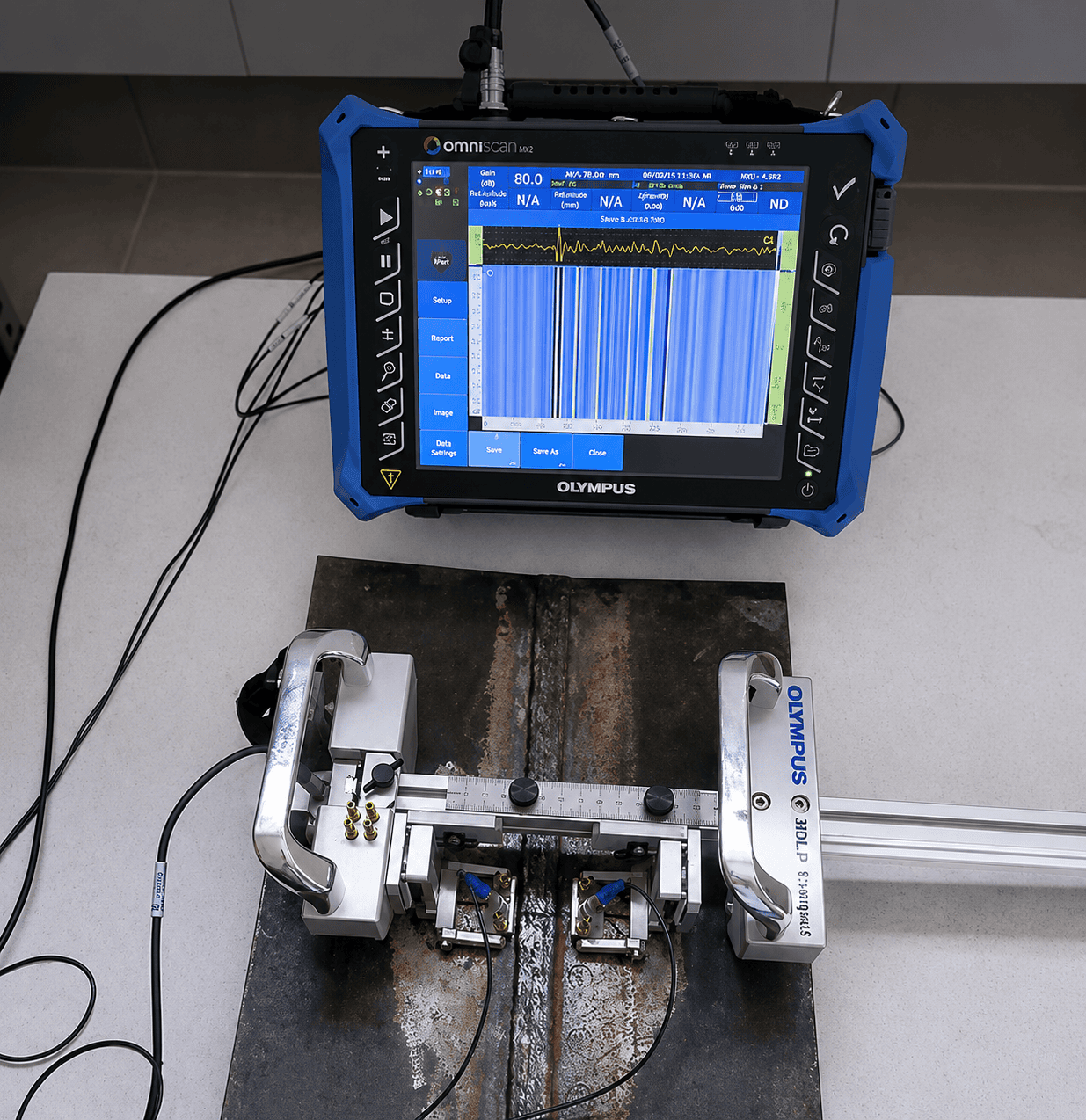
How TOFD works
Two angled longitudinal-wave probes face each other across the weld at a fixed separation, the probe centre spacing (PCS). The beams are deliberately wide, so a single pass covers the full weld thickness.
Four signals arrive at the receiver, in this order:
- Lateral wave — travelling just under the scanning surface, the first arrival
- Upper tip diffraction — from the top of a discontinuity
- Lower tip diffraction — from the bottom of the same discontinuity
- Back-wall echo — reflected from the far surface, the last arrival
Depth follows from arrival time. Because the lateral wave and back-wall echo mark the two surfaces, everything in between is referenced against them. Through-wall height is simply the depth difference between the upper and lower tip signals.
The output is a greyscale D-scan: scan distance along one axis, time of flight along the other. Defects appear as characteristic arcs between the lateral wave and the back-wall echo. An experienced interpreter reads defect type from the pattern — a crack, a lack of fusion and a slag inclusion each look different.
Phase inversion
Tip diffraction signals show a phase relationship that distinguishes the top of a defect from the bottom. Reading phase correctly is what separates competent TOFD interpretation from guessing, and it is not something the instrument does for the operator.
Where TOFD excels
- Through-wall sizing. The primary reason to specify it. Sub-millimetre accuracy is achievable under favourable conditions
- Thick-section welds — a single pass covers full thickness where conventional UT would need many
- Long, repetitive welds — pipe spools, vessel seams, storage tanks
- Fitness-for-service assessment, where defect height feeds directly into engineering critical assessment
- In-service crack growth monitoring — repeat scans compared against a baseline
- Orientation-independent detection of planar defects
Limitations — the ones that decide whether TOFD alone is enough
Dead zones. This is the defining limitation.
Directly below the scanning surface, the lateral wave masks any signal arriving at nearly the same time. At the far surface, the back-wall echo does the same. The result is a blind band at both the cap and the root, typically a few millimetres, depending on probe frequency, wedge angle and PCS.
Those bands are exactly where many real defects live — root defects and toe cracks. TOFD alone should not be specified for a weld where near-surface defects are the concern. In practice TOFD is paired with PAUT or angle-beam pulse-echo, which cover the dead zones while TOFD sizes what lies between them. Any procedure offering TOFD as a standalone substitute for full weld inspection deserves a question about coverage.
Minimum thickness. ISO 10863 applies from about 6 mm. Below that the dead zones consume most of the section. For thin walls, use PAUT or digital radiography.
Both-side access. The probe pair must straddle the weld. Where only one side is reachable, TOFD is not available.
Transverse defects. Defects running across the weld axis are poorly detected by a standard longitudinal scan and require additional passes at different orientations.
Small defects near the surface may be missed even outside the strict dead zone, because diffracted energy is weak and the nearby lateral wave dominates.
Interpretation. The D-scan image is not self-explanatory. Reading arcs, phase and mode-converted signals correctly requires trained, experienced personnel — ISO 9712 Level 2 minimum, procedures approved at Level 3.
A note on detectability claims
Published figures putting TOFD detectability at 90–95% come from specific comparative trials on specific defect populations. They are not a property of the method that transfers to arbitrary applications. Detectability depends on defect type, size, orientation, material, thickness and procedure — as does sizing accuracy. Any quoted figure should be read as “achievable under conditions resembling those of the trial”, not as a specification.
Standards
| Scope | Standard |
|---|
| TOFD of welds — technique | ISO 10863 |
| TOFD — acceptance levels | ISO 15626 |
| General ultrasonic principles | ISO 16810 |
| Personnel certification | ISO 9712 |
| US practice | ASME BPVC Section V, Article 4, Appendix III |
| Combined PAUT + TOFD (welds) | ISO 13588 in conjunction with ISO 10863 |
ASME Code Case 2235 provides the basis for ultrasonic examination in lieu of radiography on certain pressure vessel welds, subject to its conditions.
TOFD, PAUT or radiography?
| TOFD | PAUT | Radiography |
|---|
| Through-wall sizing | Best | Good | Not available |
| Planar defect detection | Very good | Very good | Poor |
| Volumetric porosity | Limited | Adequate | Best |
| Near cap and root | Dead zones | Good | Good |
| Minimum thickness | ~6 mm | A few mm | Very thin possible |
| Access required | Both sides of weld | One side | Both sides of wall |
| Radiation controls | None | None | Controlled area |
| Speed on long welds | Very fast | Fast | Slow |
The realistic answer for demanding weld work is TOFD and PAUT together: PAUT covers the dead zones and characterises defects, TOFD sizes them precisely. Many procedures specify exactly this combination, and it is generally a stronger scope than either alone.
Frequently asked questions
What is the difference between TOFD and conventional ultrasonic testing?
Conventional UT measures reflected echo amplitude, which varies strongly with defect orientation. TOFD measures the arrival time of energy diffracted from defect tips, which is far less orientation-dependent — giving much better through-wall sizing.
How accurate is TOFD sizing?
Sub-millimetre through-wall accuracy is achievable under favourable conditions, and TOFD is generally the most accurate ultrasonic sizing technique available. Actual accuracy depends on defect type, thickness, material and setup, so it should be established for the specific application rather than assumed.
What are TOFD dead zones?
Blind bands immediately below the scanning surface and at the back wall, where the lateral wave and back-wall echo mask defect signals. Typically a few millimetres each. They are the reason TOFD is normally combined with PAUT or pulse-echo.
Can TOFD be used on thin-walled components?
Not below roughly 6 mm, the lower limit of ISO 10863. Dead zones would consume most of the section. Use PAUT or digital radiography instead.
Can TOFD replace radiography?
Frequently yes, particularly on thick sections and long welds, and with no radiation controls required. Radiography remains preferable for fine volumetric porosity and is still mandatory under some specifications.
Does TOFD require access to both sides of the weld?
Yes — the transmitting and receiving probes must be positioned on opposite sides. This is a firm constraint, not a preference.
Need TOFD to ISO 10863, or combined TOFD and PAUT?
Our ISO 9712 certified inspectors perform encoded TOFD on pipelines, pressure equipment and structural welds across Europe.
→ TOFD inspection services · Request a quote