Ultrasonic testing (UT) uses high-frequency sound to find discontinuities inside a component without cutting it open. A probe sends a short pulse into the material; wherever the pulse meets a boundary — the back wall, a crack, an inclusion — part of the energy reflects back and is timed and measured. From that echo an inspector determines how deep the reflector lies and how large it is relative to a known reference.
UT is the most widely used volumetric NDT method in heavy industry, and the method of choice for planar defects such as cracks and lack of fusion, which radiography frequently misses.
How ultrasonic testing works
A piezoelectric crystal in the probe converts an electrical pulse into mechanical vibration, typically between 0.5 and 10 MHz. The pulse travels through the material at a velocity fixed by the material itself — roughly 5,900 m/s for longitudinal waves in steel — and reflects wherever acoustic impedance changes.
The instrument displays amplitude against time of flight. Because velocity is known, time converts directly to depth. Three quantities come out of a single echo:
- Depth — from time of flight
- Equivalent size — from amplitude, compared against a reference reflector
- Nature and orientation — from echo shape, behaviour as the probe moves, and response to different beam angles
Frequency is a trade-off, not a setting
Higher frequency gives better resolution and detects smaller reflectors, but attenuates faster and penetrates less. Lower frequency penetrates coarse-grained and thick material but resolves less detail.
In practice: 2–5 MHz for most steel work, 1–2 MHz for heavy sections, coarse-grained castings and austenitic material, 5–10 MHz for thin sections and fine-grained material where small defects matter.
Techniques
Straight beam (0°) — the beam enters perpendicular to the surface. Ideal for laminations, inclusions and thickness measurement, because these lie parallel to the surface and present a large reflecting face.
Angle beam — the beam is refracted into the material at an angle, typically 45°, 60° or 70°. Essential for welds, where the defects of interest lie in the fusion faces and would be invisible to a straight beam. See our guide to angle beam testing.
Dual element (TR) — separate transmitter and receiver crystals. Reduces the near-surface dead zone, so it is the standard choice for corrosion thickness measurement and near-surface discontinuities.
Phased array (PAUT) — an array of elements pulsed with controlled delays, steering and focusing the beam electronically. Produces a sectorial image rather than a single trace, and records the full data set. See phased array ultrasonic testing.
TOFD — measures diffracted signals from defect tips rather than reflected amplitude, which makes it markedly better at through-wall sizing. See time of flight diffraction.
Data can be presented as A-scan, B-scan or C-scan — explained in our article on A-scan, B-scan and C-scan methods.
Calibration: why the reference matters more than the instrument
A UT result is meaningless without a reference. Sensitivity is set before testing using calibration blocks — commonly V1 (ISO 2400) and V2 (ISO 7963) — and evaluation is made against one of two systems:
- DAC (Distance Amplitude Correction) — a curve built from identical artificial reflectors at increasing depths, compensating for attenuation and beam spread
- DGS / AVG — a calculated system relating echo amplitude to an equivalent flat-bottom hole at a given depth
Both express findings as equivalent reflector size, not physical size. A rough, irregular discontinuity reflects far less energy than a flat disc of the same area, so the real defect may be considerably larger than the equivalent value suggests. ASTM A388 states this explicitly. Any report that presents an equivalent size as a physical measurement is misreading its own data.
Calibration is also why instrument condition matters: see our notes on calibration of ultrasonic flaw detectors and calibration of thickness gauges.
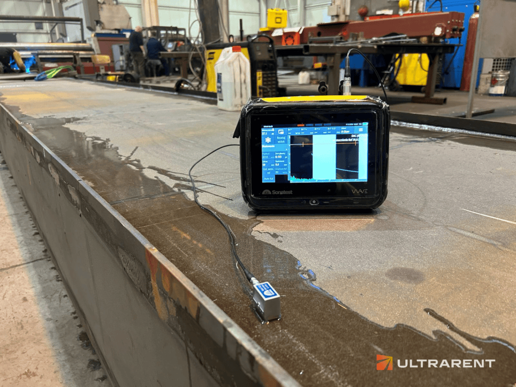
What UT detects well
- Planar defects — cracks, lack of fusion, lack of penetration. UT’s principal strength, and the reason it complements radiography rather than duplicating it
- Laminations in plate, bar and pipe
- Non-metallic inclusions and inclusion clusters
- Shrinkage cavities and porosity in castings and forgings
- Hydrogen flakes in heavy forgings
- Wall thickness and corrosion loss — see ultrasonic thickness measurement
What UT detects well
- Planar defects — cracks, lack of fusion, lack of penetration. UT’s principal strength, and the reason it complements radiography rather than duplicating it
- Laminations in plate, bar and pipe
- Non-metallic inclusions and inclusion clusters
- Shrinkage cavities and porosity in castings and forgings
- Hydrogen flakes in heavy forgings
- Wall thickness and corrosion loss — see ultrasonic thickness measurement
Standards
| Scope | Standard |
|---|
| General principles | ISO 16810 |
| Sensitivity and range setting | ISO 16811 |
| Discontinuities perpendicular to the surface | ISO 16826 |
| Characterisation and sizing | ISO 16827 |
| Calibration blocks V1 / V2 | ISO 2400 / ISO 7963 |
| Welds — technique | ISO 17640 |
| Welds — acceptance levels | ISO 11666 |
| Forgings, ferritic and martensitic | EN 10228-3 |
| Forgings, austenitic and duplex | EN 10228-4 |
| Steel castings | EN 12680-1, -2 |
| Ductile iron castings | EN 12680-3 |
| Plate | EN 10160 (quality classes S0–S3 body, E0–E4 edges) |
| Stainless plate | EN 10307 |
| Bar | EN 10308 |
| Steel tube and pipe | ISO 10893-8 (laminations), -10 (longitudinal/transverse), -11 (weld seam) |
| PAUT | ISO 13588, acceptance ISO 19285 |
| TOFD | ISO 10863 |
| Personnel certification | ISO 9712 |
ASTM equivalents (North American specifications): A388 forgings, A609 steel castings, A435 and A578 plate, E164 welds. ASME BPVC Section V Articles 4 and 5 govern UT for pressure equipment.
The governing standard is not interchangeable. Applying a forging standard to a plate, or a general-purpose casting standard to a highly loaded component, produces acceptance criteria that were never intended for that product — and either rejects sound material or passes a real defect. Specify the product type and its service duty when ordering.
Under ISO 9712, personnel are certified by method and level:
- Level 1 — performs testing under supervision to written instructions
- Level 2 — selects the technique, sets up the equipment, evaluates results against acceptance criteria, and reports
- Level 3 — writes and approves procedures, interprets standards, and holds technical responsibility
For UT, evaluation against acceptance criteria requires Level 2 as a minimum. Procedure approval requires Level 3.
Frequently asked questions
Can ultrasonic testing detect cracks? Yes, and it is generally the most capable method for them, provided the beam angle is chosen so the crack is not parallel to the beam. This is where UT outperforms radiography, which frequently misses tight planar defects.
How deep can ultrasonic testing detect? Depth is limited by attenuation, not by the method. In fine-grained steel, several metres are achievable at low frequency. In coarse-grained or austenitic material, useful range may fall to tens of millimetres.
Does UT give the actual size of a defect? No. Conventional UT reports an equivalent reflector size derived from amplitude. The physical discontinuity may be substantially larger. TOFD and PAUT provide better through-wall sizing.
Ultrasonic testing or radiography? UT for planar defects, thick sections and depth sizing; radiography for volumetric defects and a permanent image record. Many codes require both. See ultrasonic testing or radiography.
Can UT be used on austenitic stainless steel? Yes, but with reduced sensitivity and usually at lower frequency, under EN 10228-4 rather than -3. Coarse, anisotropic weld structures may require PAUT with specialised probes.
Need ultrasonic testing to a specific standard? Our ISO 9712 Level 2 and 3 certified inspectors perform conventional UT, PAUT, TOFD and TFM across Europe. → Ultrasonic testing services · Request a quote
Reviewed by — Bartosz Zuberek, UT Level 3 to ISO 9712