Phased array ultrasonic testing (PAUT) uses a probe containing many small piezoelectric elements, each pulsed with its own precisely controlled time delay. By varying those delays, the beam can be steered to different angles, focused at chosen depths, and swept across a volume — electronically, without moving the probe.
The practical result is that one probe does the work of several conventional ones, and the inspection produces a recorded, reviewable image rather than a live trace that disappears when the operator lifts the probe.
In a conventional probe a single crystal fires at once, producing one beam at one fixed angle determined by the wedge.
In a phased array probe — typically 16, 32 or 64 elements — the instrument fires each element at a slightly different moment. The individual wavefronts interfere, and their combined front takes a shape determined entirely by the delay pattern:
- Equal delays → a straight beam, as from a conventional probe
- Linearly increasing delays → the wavefront tilts, steering the beam to an angle
- Symmetrical delays, shortest at the edges → the wavefront curves inward, focusing the beam at a chosen depth
- Delays changed pulse by pulse → the beam sweeps, producing a sectorial image
The delay pattern for a given angle and focal depth is a focal law. A sectorial scan from 40° to 70° in 1° steps is simply 31 focal laws fired in sequence, with the results assembled into one image.
Why this matters for weld inspection
A conventional angle beam inspection of a bevelled weld requires several probes at different angles, several passes, and an operator mentally reconstructing the weld cross-section from a series of A-scans. PAUT sweeps the whole angular range in a single pass and displays the cross-section directly.
The gain is not only speed. Coverage becomes demonstrable. A recorded scan with encoder position data shows exactly which volume was examined — something a manual conventional inspection cannot prove after the fact.
Probes, wedges and encoders
Linear arrays — elements in a single row, steering in one plane. The standard choice for welds.
Matrix arrays — elements in a grid, allowing steering in two planes. Used for complex geometry and skewed defects.
Dual matrix arrays (DMA) — separate transmit and receive arrays, usually with transverse wave or longitudinal wave configurations. The standard answer for austenitic and dissimilar-metal welds, where coarse anisotropic structure defeats conventional probes.
Wedges set the nominal refraction angle; the array steers around it. A probe cannot steer usefully far beyond the wedge’s design range.
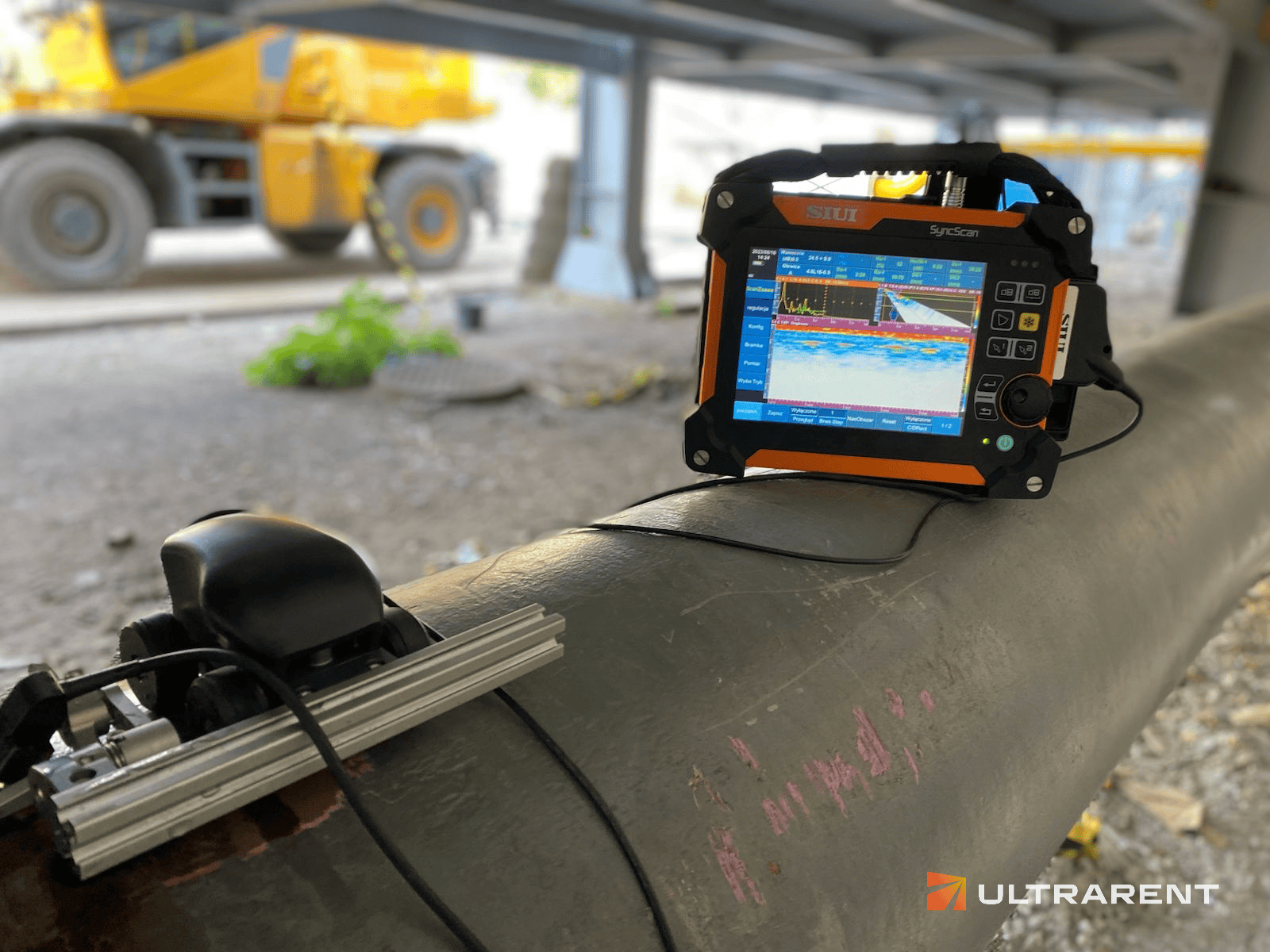
Encoders record probe position along the weld. Without an encoder the scan has no positional reference, and the recording loses much of its evidential value. Encoded scanning is what turns PAUT from a faster inspection into a documented one.
Displays
PAUT produces several views of the same data simultaneously:
- A-scan — the underlying amplitude/time trace for a single focal law
- S-scan (sectorial) — the fan-shaped cross-section through the weld; the characteristic PAUT image
- B-scan — a side view along the scan axis
- C-scan — a plan view, showing defect footprint
- D-scan — an end view
Explained in more depth in A-scan, B-scan and C-scan methods.
Calibration and setup
More setup steps than conventional UT, and each one is a place where a scan can be silently wrong:
- Element check — verifying that all elements are active; a dead element distorts every focal law
- Wedge delay calibration across the full angular range
- Velocity calibration for the material
- Sensitivity (ACG) — angle-corrected gain, equalising response across all angles
- TCG — time-corrected gain, compensating attenuation with depth
- Encoder calibration — verifying that recorded distance matches actual distance
Equipment performance itself is characterised under ISO 18563 (parts 1–3 for instruments, probes and combined systems). This is the reason to ask a contractor how they verify their array, not just which brand they own.
What PAUT detects well
- Planar defects — cracks, lack of fusion, lack of penetration. The multi-angle sweep means a defect missed at one angle is usually caught at another
- Through-wall sizing of planar defects, using tip diffraction within the sectorial image
- Thick-section welds, where conventional UT requires many passes
- Austenitic and dissimilar welds with dual matrix probes, under ISO 22825
- Complex geometry — nozzles, branch connections, node welds
- Corrosion mapping as an encoded C-scan
Limitations
Surface access and preparation. PAUT needs a smooth, clean scanning surface with room for the probe and wedge. Weld cap dressing is often required. Where access is restricted to one side or the surface cannot be prepared, radiography may be the only option.
Coupling. Ultrasound does not cross an air gap. Rough, pitted or heavily coated surfaces degrade or prevent the inspection.
Coarse grain remains a limit. Dual matrix probes extend PAUT into austenitic material, but they do not remove attenuation and scatter. Very coarse cast structures can still defeat it.
Near-surface resolution. The zone immediately under the scanning surface remains difficult, as in conventional UT. Surface-breaking defects on the near side need magnetic particle or penetrant testing.
Volumetric defects are not its strength. PAUT is excellent for planar defects. For fine distributed porosity, radiography often gives a clearer and more directly interpretable picture.
Competence is decisive. A PAUT scan can look convincing and be wrong — bad focal laws, uncalibrated encoder, missed coverage. Interpretation requires ISO 9712 Level 2 as a minimum, with procedures approved at Level 3. This is not a method where equipment substitutes for training.
Procedure qualification. Many codes require the PAUT procedure to be demonstrated on a representative mock-up with known defects before it is accepted.
Standards
| Scope | Standard |
|---|
| PAUT of welds — techniques and testing levels | ISO 13588 |
| PAUT of welds — acceptance levels | ISO 19285 |
| Equipment characterisation and verification | ISO 18563-1, -2, -3 |
| Thin-walled components | ISO 20601 |
| Austenitic and dissimilar-metal welds | ISO 22825 |
| General ultrasonic principles | ISO 16810 |
| Personnel certification | ISO 9712 |
| US practice | ASME BPVC Section V, Article 4 with mandatory appendices |
| FMC/TFM (related technique) | ISO 23864, ISO 23865 |
ASME Code Case 2235 permits ultrasonic examination in lieu of radiography for certain pressure vessel welds — the formal basis on which PAUT replaces RT in code work, subject to its conditions.
PAUT or radiography?
Neither is universally better. The decision usually comes down to five factors:
| PAUT | Radiography |
|---|
| Planar defects (cracks, LOF) | Superior | Frequently missed |
| Fine distributed porosity | Adequate | Superior |
| Through-wall sizing | Yes | No |
| Thick sections | Handled well | Limited by source energy |
| Radiation controls | None required | Controlled area, exclusion zone |
| Access | One side, prepared surface | Both sides of the wall |
| Result available | Immediately | Minutes (digital) to hours (film) |
| Record type | Encoded digital data | Image |
The operational argument is often decisive: PAUT requires no controlled area, so inspection proceeds while fabrication continues nearby. Where production cannot stop, that alone settles the question.
Frequently asked questions
How does phased array differ from conventional ultrasonic testing?
A conventional probe produces one beam at one fixed angle. A phased array probe fires many elements with controlled delays, steering and focusing the beam electronically and sweeping a range of angles in a single pass — producing a recorded cross-sectional image rather than a live trace.
Can PAUT replace radiography?
In many applications, yes, and codes such as ASME Code Case 2235 provide the formal basis. PAUT is superior for planar defects and requires no radiation controls. Radiography remains preferable for fine volumetric porosity and is still mandatory under some specifications.
Does PAUT give the actual size of a defect?
For through-wall height of planar defects, PAUT sizing is considerably more reliable than amplitude-based conventional UT, because it uses tip signals within the sectorial image. Accuracy still depends on defect type, material and procedure.
What thickness range does PAUT cover?
From a few millimetres — ISO 20601 addresses thin-walled components specifically — up to heavy sections where conventional UT becomes impractical.
Can PAUT be used on austenitic stainless steel?
Yes, with dual matrix probes and a procedure qualified under ISO 22825. Coarse anisotropic structure still limits performance and requires a technique developed for the specific weld configuration.
Is an encoder always necessary?
Not always, but unencoded scanning loses positional reference and much of the evidential value of the recording. Where the record must demonstrate coverage, encoding should be specified.