In brief
- Continuous coverage, not samples — the difference that matters
- Spot readings statistically miss pits, and pits perforate first
- PAUT C-scan for accessible surfaces; tangential radiography for insulated pipe
- The baseline is the product — repeat scans reveal rate, not just state
- Still only measures wall loss — cracks need a different method
Corrosion mapping produces a continuous image of remaining wall thickness across an area, rather than a set of individual readings. The output is a colour-coded map in which thinning is immediately visible, dimensioned and located.
The reason it exists is a limitation of the method it supplements. Ultrasonic thickness measurement reads one point at a time, and points are samples of a surface — not the surface.
Why grid readings are not enough
For uniform general corrosion, which removes wall evenly, a grid of spot readings describes the component well. Adding points adds little.
For localised attack — pitting, under-deposit corrosion, erosion at an elbow, a wet spot under insulation — the grid fails, and it fails in a specific and predictable way.
A pit a few millimetres across, sitting between two grid points, produces no reading. The grid reports healthy wall. The pit is meanwhile the thinnest point on the component and the one that will perforate first. Increasing grid density reduces but never removes this, because the sampling problem is structural: you are inferring a surface from points, and localised damage is exactly what points miss.
The consequence in practice is a leak on a line that “passed” its last thickness survey. Corrosion mapping exists to close that gap.
PAUT corrosion mapping
An encoded phased array probe is scanned across the surface. The array covers a swathe with each pass, the encoder records position, and the instrument builds a C-scan — a plan view of the area with thickness represented as colour.
What it delivers:
- Continuous coverage of the scanned area, not samples
- Minimum remaining thickness located precisely on the component
- Extent of loss — how large an affected area is, not just how deep
- Distinction between general thinning and discrete pitting, which drives different repair decisions
- A permanent digital record that can be re-analysed and compared later
Requirements and limits:
- Access to the external surface, prepared and coupled — this is the constraint that decides feasibility
- Insulation must be removed where fitted, which is often the dominant cost
- Surface condition governs coupling; heavy scale or rough coating must be dealt with
- Temperature limits apply; hot surfaces need high-temperature probes and correction
- Geometry — complex shapes, small-bore pipe and obstructions limit scanner access
See also our guide to phased array ultrasonic testing for how the array and encoder work.
Tangential radiography
For insulated pipework, removing insulation to scan ultrasonically is frequently the largest item in the budget — and on operating lines, sometimes not permitted at all.
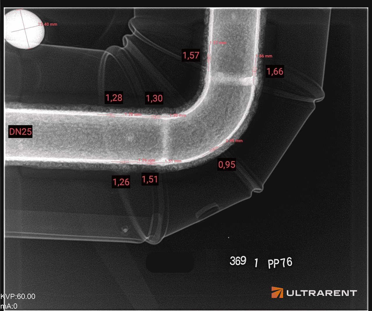
Tangential radiography takes a different route. The beam is directed at a tangent through the pipe wall, so the wall profile is projected at the edge of the image and can be measured directly from the radiograph. Insulation stays on.
Where it earns its keep:
- Corrosion under insulation (CUI) without stripping the cladding
- On-stream inspection — the line stays in service
- Small-bore pipework, where ultrasonic scanner access is impractical
- Deposit and product build-up internally, visible on the same image
- Screening long runs to find the areas that then justify detailed examination
Trade-offs: ionising radiation and therefore a controlled area; accuracy below encoded ultrasonic mapping; effectiveness dropping with wall thickness and pipe diameter; and it profiles the wall at the tangent, not the whole circumference — several exposures are needed for full coverage.
A worked example: in our case study on an ammonia refrigeration system, 100 measurement points were checked through the insulation with no shutdown, and several locations were found below 1 mm against a nominal 2.3–3.2 mm.
Our capability. Tangential radiography using gamma sources is available for projects in Poland, where we hold the required authorisation. Outside Poland we operate X-ray equipment up to 250 kV, which limits the technique to lighter sections; beyond that range we recommend PAUT mapping with insulation removed.
Choosing between them
| PAUT C-scan | Tangential radiography |
|---|
| Coverage | Continuous over scanned area | Wall profile at the tangent |
| Accuracy | Higher | Lower |
| Insulation | Must be removed | Stays on |
| Line in service | Usually must be free of product | On-stream possible |
| Radiation controls | None | Controlled area required |
| Small-bore pipe | Difficult | Well suited |
| Large flat surfaces | Well suited | Impractical |
| Output | Digital C-scan, re-analysable | Radiograph |
A common and sensible combination: tangential radiography to screen a long insulated run and find suspect areas, then insulation removal and PAUT mapping only where the screening justifies it. That sequence usually costs far less than stripping everything.
What corrosion mapping is used for
Tank shells and bottoms. Floor plates corrode from the soil side where nothing is visible. Mapping during an outage locates thin areas before they leak.
Piping circuits with known damage mechanisms — erosion-corrosion at elbows and tees, under-deposit attack in dead legs, CUI at supports and penetrations.
Pressure vessels and heat exchanger shells, particularly around nozzles and at liquid levels.
Fitness-for-service assessment. API 579 / ASME FFS-1 assessments require the profile of metal loss, not a single minimum reading. Corrosion mapping supplies exactly the input those calculations need — which is often the real reason a client commissions it.
Baseline and repeat. The first scan establishes a baseline; subsequent scans against it give corrosion rate, and rate gives remaining life. A single scan describes a state; two scans describe a trajectory, and it is the trajectory that determines when to repair, when to replace, and when the next inspection is due.
Limitations
It measures wall loss, and only wall loss. Cracks, laminations and weld defects need ultrasonic flaw detection, PAUT or surface methods. Adequate remaining thickness says nothing about stress corrosion cracking.
Coverage is what you scanned. Areas the scanner could not reach are unexamined — and should be identified on the drawing beforehand, not omitted quietly from the report.
Insulation removal often dominates cost, which is precisely why the screening-then-mapping sequence exists.
Repeatability requires discipline. Comparing scans over time only works if position, datum and technique are reproduced. Poorly referenced baseline data cannot support a rate calculation, and a corrosion rate derived from mismatched scans is worse than none.
Standards and frameworks
No single standard governs corrosion mapping as such. Applicable documents come from the inspection framework:
| Scope | Document |
|---|
| Ultrasonic thickness measurement | ISO 16809 |
| PAUT of welds — techniques | ISO 13588 |
| Piping inspection | API 570 |
| Storage tank inspection | API 653 |
| Pressure vessel inspection | API 510 |
| Fitness-for-service | API 579 / ASME FFS-1 |
| CUI management | API RP 583 |
| Personnel certification | ISO 9712 |
Because no dedicated standard exists, the written procedure carries the weight — scan plan, coverage, encoder calibration, reference points, data format and reporting. Procedure approval requires ISO 9712 Level 3 in UT.
Frequently asked questions
What is the difference between corrosion mapping and thickness measurement?
Thickness measurement gives point readings or a coarse grid. Corrosion mapping produces continuous coverage across an area as an encoded C-scan, showing where loss is and how far it extends.
Why do spot readings miss pitting?
Because they sample a surface rather than cover it. A pit between grid points produces no reading, and pits are usually the thinnest point on the component. Denser grids reduce but do not remove the problem.
Can corrosion be assessed without removing insulation?
Yes, using tangential radiography, which profiles the wall through the insulation. Accuracy is lower than ultrasonic mapping, so it is often used to screen a run and target where insulation removal is justified.
Does the installation have to be shut down?
For PAUT mapping the component normally needs to be free of process medium, though not necessarily dismantled. Tangential radiography can be performed on-stream, subject to establishing a controlled area.
How accurate is corrosion mapping?
Encoded PAUT mapping achieves high resolution on prepared surfaces. Accuracy depends on geometry, wall thickness, material, surface condition and technique — and should be established for the specific application rather than quoted generally.
Does corrosion mapping detect cracks?
No. It measures wall loss. Stress corrosion cracking, fatigue cracking and weld defects require flaw detection methods, usually PAUT together with a surface method.
Need corrosion mapping on tanks, vessels or insulated pipework?
We perform encoded PAUT C-scan mapping and digital tangential radiography across Europe, including baseline surveys for API 579 fitness-for-service assessment. ISO 9712 Level 3 in UT and RT.
→ Corrosion mapping services · Request a quote